Our staff includes certified commercial divers that can make waterfilled or underwater structures accessible for inspection.
Diving Inspection
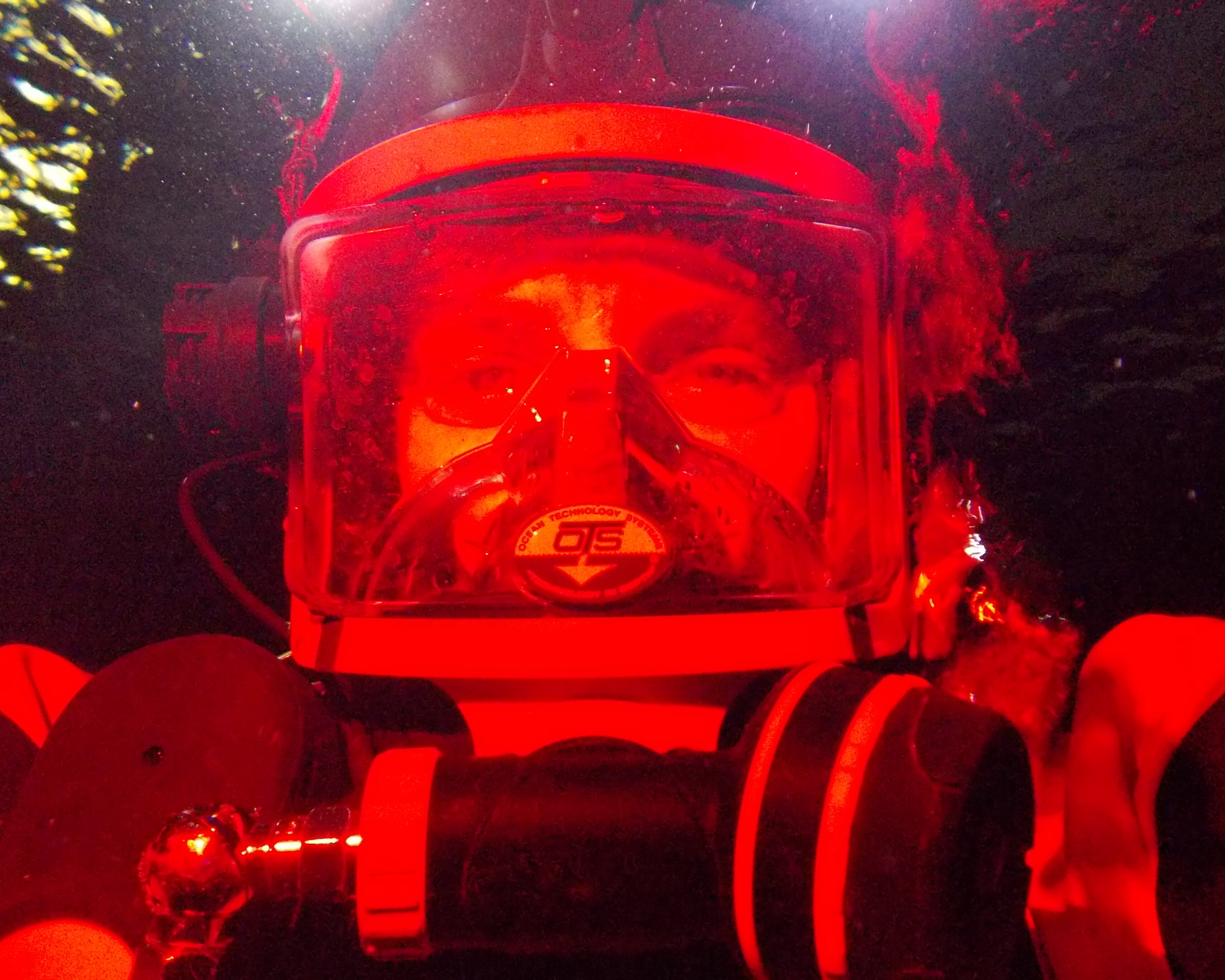
Our staff includes certified commercial divers that can make waterfilled or underwater structures accessible for inspection.